41 min to read
Computer Networking 101
Fundamentals of Computer Networking.
In the era of Cloud, having basic understanding of computer networking, how it’s work and use cases to build network is essential. Apart form it’s structure one should also keep in mind there are various ascepts of networking too like Network communication Protocols security of our Network …
In this we are gonna cover all the basic fundamentals of Networking.
Although all the networks are built on the same principles, but let’s consider them separetely for better understandings. so first thing first start with what comes in our mind when we think about “Networking”..
What is a Network?
A network is a collection of network-enabled devices like computer, switches, routers, printers & servers. Basic networks can be a part of our day-to-day life in homes, offices and public areas. Networks allow all types of network-enabled devices to communicate.
Types of Network
In layman’s term it can be categorized into followings :-
- Personal area networks (PAN)
- Local area networks (LAN)
- Metropolitan area networks (MAN)
- Wide area networks (WAN)
Personal Area Network
PAN is a group of a computer network around an individual. eg:- Smartphone,smartwatch,tablet and laptop all are connect and share data without the need to connect to an access point or third-party network services. PAN networks typically use Bluetooth to communicate because it provides a low-power,short-range data-sharing capability. The network standards associated with a PAN are Bluetooth and IEEE 802.15.
Local Area Network
LAN is a group of computers around a single location. This location might be an organization’s office, a school, a university, a hospital, an airport, and many others. A LAN is usually privately owned and needs authentication and authorization to access. Of the different classifications of a network, a LAN is by far the most commonly used.
Metropolitan Area Network
MAN is a group of computer networks which provides networking capabilities between two different locations within a city or metropolitan area to provide a single extensive network. Typically, a MAN requires a dedicated and source connection b/w each LAN joined to the MAN.

Wide Area Network
A wide area network (WAN) provides networking capabilities between two different geographical locations locally or worldwide. For example, a WAN is used to connect an organization’s head office with branch offices all over the country. A WAN links multiple LANs together to create one super network. As a MAN, you use a virtual private network (VPN) to manage the connection between different LANs.
Differences between LAN and WAN networks
| LAN | WAN |
|---|---|
| A LAN is a privately operated network typically contained in a single building. | A WAN is used to connected geographically separate offices to each other. Multiple organizations might operate WANs. |
| A LAN operates at speeds of 10 Gbps or higher. | A WAN typically operates at speeds of less than 1 Gbps. |
| A LAN is less congested compared to other network types. | A WAN is more congested compared to other network types. |
| A LAN can be managed and administrated in-house. | A WAN typically requires the use of a third party to configure and set up, which increases cost. |
Network Topologies
A network topology describes the physical composition of a network. Let’s look at four topologies you can choose from when you design a LAN. They are:
- Bus
- Ring
- Mesh
- Star
Bus Topology

In a bus topology, each network device is connected to a single network cable. Even though it’s the simplest type of network to implement, there are limitations to it. The first limitation is the length of the main cable or bus. The longer it gets, the higher the chance of signal dropout. This limitation constrains the physical layout of the network. All devices have to be physically located near each other, for example, in the same room. Finally, if there’s a break in the bus cable, the whole network fails.
Ring Topology

In a ring topology, each network device is connected to its neighbor to form a ring. This form of network is more resilient than the bus topology. A break in the cable ring also affects the performance of the network.
Mesh Topology

The mesh topology is described as either a physical mesh or a logical mesh. In a physical mesh, each network device connects to every other network device in the network. It dramatically increases the resilience of a network but has the physical overhead of connecting all devices. Few networks today are built as a full mesh. Most networks use a partial mesh, where some machines interconnect, but others connect through one device.
There’s a subtle difference between a physical mesh network and a logical one. The perception is that most modern networks are mesh based, since each device can see and communicate with any other device on the network. This description is of a logical mesh network and is primarily made possible through the use of network protocols.
Star Topology

The star topology is the most commonly used network topology. Each network device connects to a centralized hub or switch. Switches and hubs can be linked together to extend and build more extensive networks. This type of typology is, by far, the most robust and scalable.
Ethernet
Ethernet is a networking standard that’s synonymous with wire-based LAN networks and also used in MAN and WAN networks. Ethernet has replaced other wired LAN technologies like ARCNET and Token Ring and is an industry standard.
While Ethernet is associated with wired networks, one should keep in mind that it’s not limited to wire, since it’s used over fiber-optic links as well.
The Ethernet standard defines a framework for data transmission, error handling, and performance thresholds. It describes the rules for configuring an Ethernet network and how each element in the network interacts with each other.
Ethernet is used in the OSI model at the data link and physical layers. It formed the basis for the IEEE 802.3 Standard. This standard helped to unify network and hardware development.
In early days ethernet supported a data transmission rate of only 2.94 Mbps. In recent years, several iterations were released to keep up with the demands for increased speed. Today, rates extend up to 400 Gbps.
Types of Ethernet
- Fast Ethernet
- Gigabit Ethernet
- 10 Gigabit Ethernet
- Terabit Ethernet
Fast Ethernet
Fast Ethernet (IEEE 802.3u) was developed to support data transmission speeds of up to 100 Mbps. Faster Ethernet is also referred to as the 100BASE-TX standard.
Gigabit Ethernet
Gigabit Ethernet (IEEE 802.3ab) was developed to support faster communication networks that can support services like streaming multimedia and Voice over IP (VoIP). The 1000BASE-T standard runs 10 times faster than the 100BASE-TX standard. Gigabit Ethernet is now included in the 802.3 standards and recommended for enterprise networks. The new standard is backward compatible with the 100BASE-T and the older 10BASE-T standards.
10 Gigabit Ethernet
The 10 Gigabit Ethernet (IEEE 802.3ae) standard has a nominal data transfer speed of 10 Gbps, which is 10 times faster than its predecessor. This speed improvement is made possible only by using fiber optics. The standard now requires that 10 Gigabit Ethernet networks use area-based routing rather than broadcasting data to all nodes. In that way, network noise and traffic are reduced.
Terabit Ethernet
Terabit Ethernet offers data transfer speeds of 200 Gbps and 400 Gbps. It’s expected that Terabit Ethernet will offer speeds of 800 Gbps and 1.6 Tbps in the future.
What is Network standards?
While network protocols provide a unified method for communication, network standards govern the hardware and software that uses them.
Today, there are hundreds of thousands of hardware suppliers, yet all of their technology seamlessly integrates with your computer or network with minimal effort. Network standards provide a framework that enables the interoperability between devices.
Network standards improve the interoperability of different network-enabled devices and provide backward compatibility between product revisions and differing vendors. Official bodies that publish regulated standards are the International Telecommunication Union (ITU), the American National Standards Institute (ANSI), and the Institute of Electrical and Electronics Engineers (IEEE).
The 802 family of standards
The 802 specification covers all the physical networking standards for both Ethernet and wireless. The following table shows some of the more widely used standards.
| 802 | Overview | Basics of physical and logical networking concepts |
|---|---|---|
| 802.1 | Bridging | LAN/MAN bridging and management of the lower sublayers of OSI Layer 2 |
| 802.2 | Logical Link | Commonly referred to as the logical link control (LLC) specification |
| 802.3 |
Ethernet |
Provides asynchronous networking by using carrier sense, multiple accesses with collision detect (CSMA/CD) over coaxial cable, twisted-pair copper cable, and fiber media |
| 802.5 | Token ring | The token-passing standard for shielded copper cables and twisted-pair cable |
| 802.11 | Wi-Fi | Wireless local area network (WLAN) media access control (MAC) and physical layer (PHY) specification |
| 802.11a | Wi-Fi | Specifies a PHY that operates in 5 GHz |
| 802.11b | Wi-Fi | Enhances 802.11, adds higher data rate modes |
| 802.11d | Wi-Fi | Enhances 802.11a/b, allows for global roaming |
| 802.11e | Wi-Fi | Enhances 802.11, adds Quality of Service (QoS) features |
| 802.11g | Wi-Fi | Extends WLAN maximum data rate |
| 802.11 h | Wi-Fi | Enhances 802.11a, now resolves interference issues |
| 802.11i | Wi-Fi | Enhances 802.11, adds security for WLAN applications |
| 802.11j | Wi-Fi | Enhances 802.11a for Japanese regulatory extensions |
| 802.11n | Wi-Fi | Higher-speed standards |
| 802.12 | Demand Priority | Ethernet data rate increased to 100 Mbps |
| 802.15 | Wireless personal area networks | Support for wireless personal area networks (WPANs) |
| 802.15.1 | Bluetooth | Short-range (10 m) wireless technology |
| 802.15.3a | UWB | Short-range, high-bandwidth ultra-wideband (UWB) link |
| 802.15.4 | ZigBee | Short-range wireless sensor networks |
| 802.16 | Wireless metropolitan area networks | Covers mobile and wireless broadband access in wireless metropolitan area networks (WMANs) |
Network Infrastructure
There are several network standard-compliant devices that make up the structure of your networks. Depending on the network’s size, you might use several of these devices to build the backbone of your network. These devices are:
- Repeaters
- Hubs
- Bridges
- Switches
- Routers
What is a media access control address?
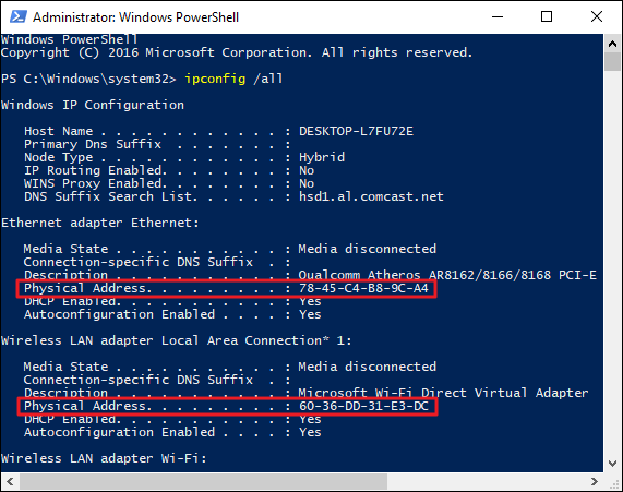
The media access control (MAC) address is a unique identifier assigned to every network-enabled device at the time of manufacture. It’s sometimes referred to as the burned-in address, the Ethernet hardware address, or a physical address.
The MAC address has a standard composition of six hexadecimal numbers separated by a colon or dash. The first three numbers of the MAC address define the manufacturer’s organizationally unique identifier (OUI) and the remaining three numbers uniquely identify the device. For example, if the MAC address is AA-6A-BA-2B-68-C1 then the OUI is AA-6A-BA and 2B-68-C1 is the device ID.
Repeater
A repeater is a two-port device that repeats network signals. Repeaters are used when network devices are some distance from each other. The repeater doesn’t modify or interpret data packets before it resends them, and it doesn’t amplify the signal. Instead, it regenerates the data packet at the original strength, bit by bit.
Bridge
A bridge divides a network into network segments and can filter and forward data packets between these segments. Bridges use the network device’s MAC address to decide the data package’s destination. Typically, a bridge is used to improve network performance by reducing unnecessary network traffic on network segments.
Hub
A hub acts as a multiport repeater on a network. Hubs are used to connect more than one device and structure the layout of a network. For example, you can cascade hubs to create network branches or as an endpoint to create a star layout with multiple user type devices. Hubs contain multiple ports that act as an input/output Ethernet connection between the hub and a network device. A hub can operate at only one speed, which is the speed of the slowest network device on the network. It doesn’t interpret or filter data packets and sends copies of each data packet to all attached devices.
Types of hubs
-
Fast Ethernet : This hub is used for 100-Mbps networks and comes as Class I and Class II type hubs. The primary difference between the two is the amount of delay in data transmission. A Class I hub introduces a signal delay of up to 140-bit times. A Class II hub has a delay of up to 96-bit times. The delay allows for the transcoding of data between different base types. Only two Class II hubs can be used in a hub-based network. Class II hubs increase the likelihood of packet collisions because of their higher speeds.
-
Dual Speed : With a traditional hub network, the speed of the network was governed by the slowest network device attached. For example, if you had 10-Mbps and 100-Mbps devices connected to a network, the speed of the whole network was only 10 Mbps. Dual-speed hubs solve the problem by acting as a bridge between the two different-speed devices.
Hubs are used for small ad-hoc networks of a few devices, but they’re rarely used at an enterprise level.
Switch
A switch combines the functionality of a bridge and a hub. It segments networks and can interpret and filter packet data to send it directly to an attached network device. Switches use the network device’s MAC address to decide the data package’s destination. A switch operates in full-duplex mode, which means it can send and receive data to and from network devices at the same time.
Features
Modern Ethernet-based switches offer more functionality and capabilities than an Ethernet hub.
- An Ethernet switch can adjust the connection speed of an inbound packet to match the connection speed of the destination network.
- Many switches now support Power over Ethernet (PoE). PoE enables network devices like Voice over IP (VoIP) phones to get power from the switch, without needing a separate power supply.
- Other modules can be attached to the switch to enable functions like port mirroring, packet sniffers, and intrusion detection systems.
Types of Ethernet switch
The two distinct types of switch are unmanaged and managed.
Unmanaged
This type of switch has no configuration capability and is designed for small office or home office environments. Packet switching occurs automatically.
Managed
This type of switch offers the means to adjust the configuration, behavior, and operation of the switch. Access to the switch configuration is either through a command-line interface (CLI) that uses Telnet or Secure Shell (SSH), Remote Console, or via a web interface.
Here’s a list of the more commonly available options to configure on a managed switch.
- Quality of Service :- Manage LAN traffic so that critical systems are given higher priority. An example is voice-data packets, which need to be delivered quickly.
- Virtual LANs :- Create logical groups of devices in their own virtual LAN. Traffic in one virtual LAN doesn’t cross over into another virtual LAN. This logical group of devices can improve the security and performance of the network.
- Spanning Tree Protocol (STP):- Build resilience into your network by defining alternative network routes in case a cable or device fails.
- Port mirroring: Use with a network analyzer to diagnose network issues and problems. During setup, the switch exports a copy of the network traffic to a single port.
- Bandwidth rate-limiting: Allow fine control of the bandwidth used by specific ports, such as high bandwidth for ports handling database or VoIP and lower bandwidths for email.
- MAC address filtering: Provide the ability to control which network devices can be used or have access through the switch.
- SNMP client : Set up and configure SNMP with your network monitoring tools.
There are two subtypes of managed switch:
- Smart: A smart switch is a halfway point between an unmanaged and a managed switch. They tend to offer only a web-based interface to manage the configuration. The available options are virtual LANs, port mirroring, and bandwidth rate limiting.
- Enterprise: The fully managed switch service previously described.
Router
Routers link networks with different ranged addresses together. They can interpret and filter data packets, and then forward them to the correct network. Routers use the network device’s IP address information to route the data package to its destination. Most routers can now detect issues with data traffic that flows to any attached network and route or reroute it around the issue. A router is also called a gateway. When you configure network devices, you’ll usually configure it with a default gateway IP address.
Interconnectivity
Routers in an interconnected network maintain a routing table that lists the preferred route between each of the networks. The router acts as the start of authority for all the network devices on its network. Routing information is shared between routers by using a routing protocol like the Border Gateway Protocol (BGP).
Types
There are several distinct classifications or types of routers available to service different network needs.
-
Access routers: Typically used in a home or small satellite offices, these routers tend to be low-cost devices with a simple routing need.
-
Distribution routers: These routers compile traffic routing data from multiple routers. Distribution routers come with more significant memory and processing power. This type of router is designed to hold vast quantities of routing information. It’s often used to manage and control the quality of service across a WAN.
-
Edge routers: An edge router operates at the boundary between your network and other networks, for example, your local network and the internet. They act as gateways to filter traffic and route it internally or forward it based on the packet header. An edge router often comes with access control or firewalls to improve the security. It might also handle DHCP and DNS services.
-
Core routers: Sometimes called enterprise routers, these routers are designed for higher bandwidths. They’re used to connect different buildings or geographic locations together. Core routers tend to have fewer features than edge routers because their primary focus is on minimizing packet loss and preventing congestion. They tend to do packet forwarding to edge routers.
Wireless router
This network device provides all the routing capabilities of a regular access router, but it also offers wireless access point functions. A wireless router or wireless access point is designed to provide a non-wired connection to your network. Any provision to access the internet or other networks is handled by an edge router associated with your network. A wireless router lets you build a different type of network called a wireless local area network.
A wireless router shouldn’t be confused with a wireless modem. A wireless modem is what you receive from your ISP for your home or office and is the device that converts the signal from the ISP into one that’s usable on a computer network. Wireless modems are typically combined with routers to allow you to create a private home or office network.
Network protocols
A network protocol is a set of conditions and rules that specify how network devices communicate on a given network. It provides a common framework for establishing and maintaining a communications channel, and how to handle errors or faults should they occur. Network protocols allow communication between different network-enabled devices, for example, laptops, tablets, smartphones, desktops, servers, and other network-enabled devices.

The network protocol is an essential building block in the design of an organization’s network architecture. There are many network protocols available. Each network protocol has many properties that govern its use and implementation.
What is a network address?
A network address is a unique identifier that identifies a network-enabled device. A network-enabled device might have more than one address type. Although there are more address types, for this discussion, we’ll focus on only two of these address types.
The first type is a media access control (MAC) address that identifies the network interface on the hardware level. The second type is an Internet Protocol (IP) address that identifies the network interface on a software level.
What is a data packet?
A data packet is a unit that’s used to describe the message two devices on a network send each other. A data packet consists of raw data, headers, and potentially also a trailer. The header contains several information items. For example, it includes the sender and destination device addresses, the size of the packet, the protocol used, and the packet number. The trailer in a data packet deals with error checking.
The concept is similar to sending someone a letter in the mail. But instead of sending several pages in one envelope, each page is sent in a separate envelope. Enough information is sent in each envelope to allow the recipient to piece together the complete message after they have all the pages.
What is a datagram?
A datagram is considered the same as a data packet. Datagrams commonly refer to data packets of an unreliable service, where delivery can’t be guaranteed.
What is routing?
Routing, in the context of networks, refers to the mechanism used to make sure that data packets follow the correct delivery path between the sending and receiving devices on different networks.
For example, think about the PC you’re using and the server that’s serving the page you’re currently reading. Multiple networks might connect your PC and the server, and various paths might be available between these two devices.
Protocol categories
Several types of applications and hardware devices depend on specific network protocols on a typical network. For example, browsing the internet by using a web browser relies on a different protocol than sending or receiving an email. Converting the data that you see in the browser and sending this information over the network requires another protocol.
Protocols fall into three categories:
- Network communication protocols
- Network security protocols
- Network management protocols
Network communication protocols
Communication protocols focus on establishing and maintaining a connection between devices. As you work with different devices and network services, you’ll make use of various network communication protocols.
First, we need to define three foundational protocols of all internet-based networks. These three protocols are Transmission Control Protocol (TCP), Internet Protocol (IP), and User Datagram Protocol (UDP). These protocols are concerned with the logical transmission of data over the network.
-
Transmission Control Protocol :TCP chunks up data into data packets that can be sent securely and quickly while minimizing the chance of data loss. It provides a stable and reliable mechanism for the delivery of data packets across an IP-based network. Even though TCP is an effective connection-oriented protocol, it has overhead.
-
Internet Protocol : IP is responsible for the addressing of a data packet. IP encapsulates the data packet to be delivered and adds an address header. The header contains information on the sender and recipient IP addresses. This protocol isn’t concerned about the order in which the packets are sent or received. It also doesn’t guarantee that a packet will be delivered, only the address.
-
User Datagram Protocol : UDP is a connectionless protocol that offers a low-latency and loss-tolerant implementation. UDP is used with processes that don’t need to verify that the recipient device received a datagram.
-
Hypertext Transfer Protocol (HTTP) : The HTTP protocol uses TCP/IP to deliver web page content from a server to your browser. HTTP can also handle the download and upload of files from remote servers.
-
File Transfer Protocol (FTP) : FTP is used to transfer files between different computers on a network. Typically, FTP is used to upload files to a server from a remote location. While you can use FTP to download files, web-based downloads are typically handled through HTTP.
-
Post Office Protocol 3 (POP3) : POP3 is one of three email protocols. It’s most commonly used by an email client to allow you to receive emails. This protocol uses TCP for the management and delivery of an email.
-
Simple Mail Transfer Protocol (SMTP) : SMTP is another one of the three email protocols. It’s most commonly used to send emails from an email client via an email server. This protocol uses the TCP for management and transmission of the email.
-
Interactive Mail Access Protocol (IMAP) : IMAP is the more powerful of the three email protocols. With IMAP and an email client, you can manage a single mailbox on an email server in your organization.
Network security protocols
Network security protocols are designed to maintain the security and network of data across your network. These protocols encrypt in-transmission messages between users, services, and applications.
Network security protocols use encryption and cryptographic principles to secure messages.
- Secure Socket Layer (SSL) : SSL is a standard encryption and security protocol. It provides a secure and encrypted connection between your computer and the target server or device that you accessed over the internet.
-
Transport Layer Security (TLS) : TLS is the successor to SSL and provides a stronger and more robust security encryption protocol. Based on the Internet Engineering Task Force (IETF) standard, it’s designed to stop message forgery and tampering and eavesdropping. It’s typically used to protect web browser communications, email, VoIP, and instant messaging. While TLS is now used, the replacement security protocol is often still called SSL.
-
Hypertext Transfer Protocol Secure (HTTPS) : HTTPS provides a more secure version of the standard HTTP protocol by using the TLS or SSL encryption standard. This combination of protocols ensures that all data transmitted between the server and the web browser is encrypted and secure from eavesdropping or data packet sniffing. The same principle is applied to the POP, SMTP, and IMAP protocols listed previously to create secure versions known as POPS, SMTPS, and IMAPS.
-
Secure Shell (SSH) : SSH is a cryptographic network security protocol that provides a secure data connection across a network. SSH is designed to support command-line execution of instructions, which includes remote authentication to servers. FTP uses many of the SSH functions to provide a secure file transfer mechanism.
- Kerberos : This validation protocol provides a robust authentication for client-server-based applications through secret-key cryptography. Kerberos assumes that all endpoints in the network are insecure. It enforces strong encryption for all communications and data at all times.
Network management protocols
Network administrators need to monitor their networks and any devices attached to them. Each device in your network exposes some indicators about the state and health of the device. These indicators are requested by the network administrator tool and can be used for monitoring and reporting.
Two network management protocols are available:
-
Simple Network Management Protocol (SNMP) : SNMP is an internet protocol that allows for the collection of data from devices on your network and the management of those devices. The device has to support SNMP to gather information. Devices that typically support SNMP include switches, routers, servers, laptops, desktops, and printers.
-
Internet Control Message Protocol (ICMP) : ICMP is one of the protocols included within the Internet Protocol suite (IPS). It allows network-connected devices to send warning and error messages, along with operation information about the success or failure of a connection request, or if a service is unavailable. Unlike other network transport protocols like UDP and TCP, ICMP isn’t used to send or receive data from devices on the network.
Ports
A port is a logical construct that allows the routing of incoming messages to specific processes. There’s a particular port for every type of IPS. A port is an unsigned 16-bit number in the range 0 to 65535 and is also known as a port number. Ports are assigned by the sending TCP or UDP layer based on the communications protocol used.
There are specific port numbers reserved for every service. The first 1,024 ports, called the well-known port numbers, are reserved for the commonly used services. The high-numbered ports, called the ephemeral ports, are unreserved and used by dedicated applications.
Every port links to a specific service or communications protocol. It means that the target network device, say a server, can receive multiple requests on each port and service each of them without conflict.
Well-known port numbers
The Internet Assigned Numbers Authority (IANA) manages the allocation of port numbers, the regional assignment of IP addresses, and Domain Name System (DNS) root zones. IANA also manages a central repository for protocol names and the registry used in internet protocols.
| Port Number | Assignment |
|---|---|
| 20 | File Transfer Protocol for data transfer |
| 21 | File Transfer Protocol for command control |
| 22 | Secure Shell for secure authentication |
| 23 | Telnet remote authentication service for unencrypted text messages |
| 25 | Simple Mail Transfer Protocol for email routing |
| 53 | Domain Name System service |
| 80 | Hypertext Transfer Protocol for use in the web |
| 110 | Post Office Protocol |
| 119 | Network News Transfer Protocol (NNTP) |
| 123 | Network Time Protocol (NTP) |
| 143 | Internet Message Access Protocol for management of digital mail |
| 161 | Simple Network Management Protocol |
| 194 | Internet Relay Chat (IRC) |
| 443 | HTTP Secure HTTP over TLS/SSL |
Internet Protocol suite
The Internet Protocol suite is a collection of communication protocols, also called a protocol stack. It’s also sometimes referred to as the TCP/IP protocol suite since both TCP and IP are primary protocols used in the suite.
The IPS is an abstract, layered networking reference model. The IPS describes the different layered protocols used to send and receive data on the internet and similar networks.
The IPS model is one of several similar networking models that varies between three and seven layers. The best-known model is the Open Systems Interconnection (OSI) networking reference model. We’re not going to cover the OSI model here. A documentation link is available in the “Learn more” section at the end of this module.

-
Application layer : The top layer of this stack is concerned with application or process communication. The application layer is responsible for determining which communication protocols to use based on what type of message is transmitted. For example, the layer assigns the correct email protocols such as POP, SMTP, or IMAP if the message is email content.
-
Transport layer : This layer is responsible for host-to-host communication on the network. The protocols associated with this layer are TCP and UDP. TCP is responsible for flow control. UDP is responsible for providing a datagram service.
-
Internet layer : This layer is responsible for exchanging datagrams. A datagram contains the data from the transport layer and adds in the origin and recipient IP addresses. The protocols associated with this layer are IP, ICMP, and the Internet Protocol Security (IPsec) suite.
-
Network access layer : The bottom layer of this stack is responsible for defining how the data is sent across the network. The protocols associated with this layer are ARP, MAC, Ethernet, DSL, and ISDN.
What is the Address Resolution Protocol?
The Address Resolution Protocol (ARP) is a communications protocol within the Internet Protocol suite. It’s a request-response protocol used to resolve the media access control (MAC) address for a given IP address. ARP supports many data link layer technologies, such as Internet Protocol version 4 (IPv4), DECnet, and PUP. When an Internet Protocol version 6 (IPv6) address is resolved, the Neighbor Discovery Protocol (NDP) is used instead of ARP. Without ARP, there would be no means to resolve an IP address to a physical device address.
There’s also the Reverse Address Resolution Protocol (RARP), which retrieves an IP address based on the given MAC address.
What is TCP/IP?
The Transmission Control Protocol/Internet Protocol is a collection of different communication protocols that support and define how network-enabled devices interconnect with each other over an IP-based network. At its heart are two key protocols: TCP and IP. TCP/IP makes the internet possible, as well as private and public networks like intranets and extranets.
TCP/IP defines the way data is shared between network-enabled devices by defining the end-to-end communication process. It manages how the message is broken down into packets of data, which are sometimes known as datagrams. TCP/IP also determines how the packet is addressed and transmitted, routed, and received. TCP/IP can determine the most efficient route across a network.
The TCP/IP model is designed to be stateless. This design means the network stack treats each request as new because it isn’t related to the previous request. One part of the TCP/IP model isn’t stateless. The transport layer operates in a stateful mode because it maintains a connection until all the packets in the message are received.
TCP/IP is an open standard. It’s governed, but it’s not owned by any one organization, so it works with all operating systems, networks, and hardware.
TCP/IP model layers
The TCP/IP model is made up of four distinct layers. Each layer uses a different type of protocol. Notice how the TCP/IP model is similar to the Internet Protocol suite discussed earlier.
-
Application layer : The application layer is responsible for determining which communication protocols are used. This layer includes HyperText Transfer Protocol (HTTP), DNS, File Transfer Protocol (FTP), Internet Message Access Protocol (IMAP), Lightweight Directory Access Protocol (LDAP), Post Office Protocol (POP), Simple Mail Transfer Protocol (SMTP), Simple Network Management Protocol (SNMP), Secure Shell (SSH), Telnet, and TLS/SSL.
- Transport layer : This layer splits the application data into manageable ordered chunks by using the right port for the application protocol that’s used. The protocols associated with this layer are TCP and the User Datagram Protocol (UDP).
- Internet layer : Also known as the network layer, this layer ensures the data packet gets to its destination. The protocols associated with this layer are IP, IPv4, IPv6, Internet Control Message Protocol (ICMP), and Internet Protocol Security (IPsec).
- Network access layer : This layer is responsible for defining how the data is sent across the network. The protocols associated with this layer are ARP, MAC, Ethernet, digital subscriber line (DSL), and Integrated Services Digital Network (ISDN).
Internet Protocol standards
The Internet Protocol only provides a logical addressing system that’s used to route and forward messages to their destinations.
Today, there are two Internet Protocol versions that work within networks.
IPv4
Internet Protocol version 4 was released in 1983 and is the standard for all packet-switch-based networks in use today. IPv4 uses a 32-bit address space that gives an upper limit of 4,294,967,296 (4.3 billion) unique logical IP addresses. A large number of these available IP addresses are reserved for a specific purpose, for example, private networks, local hosts, internet relays, documentation, and subnets.
Structure of an IPv4 address
The structure of an IPv4 address is four decimal numbers in the range of 0 to 255, each separated with a dot. It’s also known as the dotted-decimal format. An example of an IP address is 192.168.0.1.
Parts of an IPv4 address
There are two parts to an IP address, the network and the host. Let’s use the address 192.168.0.1 as an example.
The network part of an IP address covers the first set of decimal numbers. In the example, that’s 192.168.0. This number is unique to the network and specifies the class of the network. There are a number of network classes available, described next.
The host part of the IP address covers the next set of decimal numbers. In the example, that’s 1. This number represents the device and has to be unique within the network to avoid address conflicts. Each device on a network segment must have a unique address.
IPv4 address classes
The Internet Protocol’s local address space is split into five logical classes or ranges of IP addresses, each represented by a letter of the alphabet.
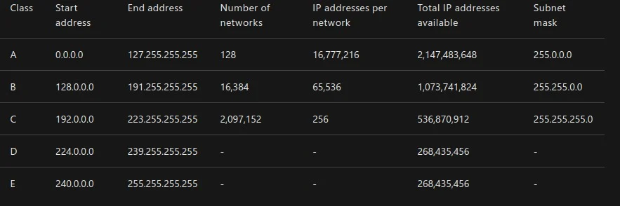
For classes A, B, and C, the start and end IP addresses are reserved and shouldn’t be used. Class D is reserved for multicast traffic only. Class E is reserved and can’t be used on public networks, like the internet.
In the previous table, the last column is marked as a subnet mask. The subnet mask uses the same format of the IP address. But its purpose is to identify valid IP addresses in an IP range.
For example, assume you have an IP address range that starts at 192.168.0.1, and you have a subnet of 255.255.255.0.You’ll apply the subnet mask in the following way. For each address segment value specified as 255 in the mask, the corresponding address segment is static. When you want to pick an IP address, you have to pick an address that matches 192.168.0. Where the segment has a value of 0, you’re allowed to use any value between 0 to 255. A subnet mask of 255.255.255.0 gives an IP address range of 192.168.0.0 to 192.168.0.255, which are valid values to select.
What is a subnet?
A subnet defines one or more logical networks within the class A, B, or C network. Without subnets, you’re restricted to a single network in each of the class A, B, or C networks.
An IP address, also known as a network address or routing prefix, represents the address of the device or computer to send the packet of data. A subnet, or host address, represents which network or subnetwork to use. A subnet is a 32-bit number framed by using the dotted-decimal format. For example, 255.255.255.0 is a standard subnet mask.
In an IPv4 network, for a packet of data to be routed to the correct network and the right network device, a routing prefix is needed. A routing prefix is created by taking the subnet mask and applying a bitwise AND to the IP address.
A more common way to define the subnet and the routing prefix is to use the Classless Interdomain Routing (CIDR) notation. CIDR applies to the IP address as the number of bits you want to allocate to your subnet. Using CIDR notation, at the end of the IP address, add a “/” and then the number of bits. For example, 198.51.100.0/24 is the same as using the dotted-decimal format subnet mask 255.255.255.0. It offers an address range of 198.51.100.0 to 198.51.100.255.

Subnets allow multiple subnetworks to exist within one network. They can be used to enhance routing performance. Subnets can be arranged hierarchically to create routing trees.
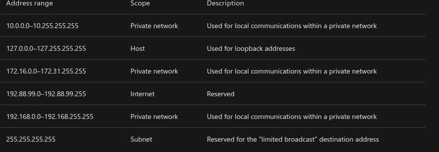
Special-use addresses :
Each of the classes has restrictions on the ranges of IP addresses that can be used. This table shows the more common ones.
IPv4 address space exhaustion
Soon after the introduction of IPv4, it became apparent that the pool of available IP addresses was being consumed faster than was expected. For example, think about the number of mobile devices that have been released in the last couple of years.
Several solutions were introduced to mitigate the threat of running out of IP addresses. These ideas included network address translation (NAT), classful networks, and CIDR. In the 1990s, IPv6 was created to increase the number of IP address spaces to 128 bits. IPv6 was introduced commercially in 2006.
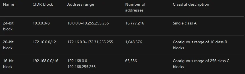
Private IP addressing
In classes A, B, and C, a range of IP addresses are set aside for private networks. These IP ranges aren’t accessible via the internet. All public routers ignore any packets sent to them that contain such an address.
Network devices on a private network can’t communicate with devices on a public network. Communication can happen only through network address translation at a routing gateway.
The only way to connect two private networks in different geographical areas is to use a virtual private network (VPN). A VPN encapsulates each private network packet. The VPN can further encrypt the packet before it sends it across a public network from one private network to another private network.
IPv6
Internet Protocol version 6 is the latest version of the IP standard. IPv6 was designed and developed by the Internet Engineering Task Force (IETF) to address the problem of IPv4 logical address exhaustion and to eventually replace the IPv4 standard. It was adopted as a recognized internet standard in July 2017.
IPv6 uses a 128-bit address space, which allows 2128 addresses. This amount is approximately 7.9x1028 times more than IPv4.
IPv4 and IPv6 weren’t designed to be interoperable, which has slowed down the transition to the newer IPv6 standard.
IPv6 also introduced several benefits:
- Simplified network configuration: IPv6 has address autoconfiguration built into the protocol. For example, a router broadcasts the network prefix and the network device can append its MAC address to self-assign a unique IPv6 address.
- Security: IPsec is built into IPv6.
- New service support: IPv6 eliminates the need for NAT, which makes it easier to create peer-to-peer networks.
- Multicast and anycast functionality: Multicast allows for the broadcast of messages in a one-to-many fashion. Anycast allows a single destination to have multiple routing paths to two or more endpoint destinations.
Structure of an IPv6 address
The structure of IPv6 is different from IPv4. Instead of four decimal numbers, it uses eight groups of four hexadecimal numbers called a hexadectet. Each hexadectet is separated with a colon. A full IPv6 address looks like this: 2001:0db8:0000:0000:0000:8a2e:0370:7334.
The new standard allows for the address to be simplified by using the following rules:
- One or more leading zeros from any group can be removed, so 0042 becomes 42.
- Consecutive sections of zeros are replaced with a double colon (::), which can be used only once in an address.
The shortened version of the IPv6 example is 2001:db8::8a2e:370:7334. Notice that all the instances of 0000 are removed.
DNS
The Domain Name System is a decentralized lookup service that translates a human-readable domain name or URL into the IP address of the server that’s hosting the site or service. The worldwide distributed nature of DNS is a vital component of the internet. DNS has been in use since its inception in 1985.
A DNS server serves two purposes. The first is to maintain a cache of recently searched-for domain names, which improves performance and reduces network traffic. The second is to act as the start of authority (SOA) for all the domains under it. When a DNS server is looking to resolve a domain name that isn’t held in its cache, it starts with the highest level, the dot, and then works down the subdomains until it finds the DNS server acting as the SOA. Once found, it stores the IP address of the domain in its local cache.
The DNS also holds specific records that relate to the domain. These records include the SOA, IP addressing (A and AAAA), SMTP email (MX), name servers (NS), and domain name alias (CNAME) records.
Work with me
Got a security challenge, architecture review, or just want to talk through something? Book a free 30-min call.


Comments